2. Parts And Tools
This section will discuss how to choose the size of the dome for your RTI system, as well as what kind of cameras will work with the system. There’s also a rundown of what the individual parts in the part list do. Finally, there’s a brief discussion of what tools you’ll need, with a special emphasis on those specialized tools that are either absolutely necessary, or which will make construction much easier.
2.1. Choosing a Dome
RTI requires you to take photographs from a fixed position above the object of interest, but at multiple lighting angles all the same distance from the center point of the object. All points at the same distance from a single center point => sphere. But you’re only photographing one side of the object => dome. Attaching lights to the inside of the dome, pointing inwards, is probably the easiest way to handle the lights, and certainly the most common. There are alternate ways to get lights in an equiradial pattern without a dome, but those usually involve quite a bit more work and expense. Feel free to explore alternatives if you like, but from this point on, I’ll only deal with domes.
The most important initial question you have to ask yourself is, how big a dome do I need? To answer that question, you have to think about what an ideal light source would be for RTI. It would be at a constant incident intensity across the entire object you were imaging, and also all the light rays would be parallel. But unless your light source is infinitely far away from the object, that’s virtually impossible to achieve. For a perfect point light source, the intensity will drop off inversely proportional to the square of the distance (the classic inverse-square law, describing how a spherical intensity changes with distance). But LEDs are not a perfect light source in that their output light varies with angle. For the LEDs I’m using, maximum intensity occurs at an angle of 0 degrees, and drops off essentially with the cosine of the angle (the Lambertian distribution).
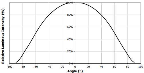
Lambertian distribution of light intensity with angle in one dimension (Source: ledsupply.com)
The further away the light is from an object, the less important both of these effects become. The radius of the sphere of light becomes larger and flatter, so that the variation in light across the object decrease; the angular width relative to the light position also decreases, so you’re up at the flatter part of the Lambertian curve centered around zero degrees. So, ideally, you’d want a dome of nearly infinite radius. Of course this is logistically impractical, and you’d you have to increase the power of the light source so that some reasonable amount of it is still available to hit the object and light it up - also not practical. So you’re going to have to live with some non-uniformity of lighting, but the bigger the dome, the relatively more uniform the light will be over a larger area.
Cultural Heritage Imaging says, based on their experience, that the maximum object size you can get good results from is roughly half the radius of the dome, e.g. a 12” diameter dome would have a radius of 6” and a maximum object size of about 3”; 18” dome has a 9” radius and a 4.5” max object size; a one-meter dome would have a radius of 50 cm, and a maximum object size of 25 cm (just shy of 10”). My personal opinion is that these are conservative numbers, and you can get useful results from objects that are up to 25% larger than these, but YMMV. I’m working on some ideas to extend these size limitations, but they’re not ready yet.
So bigger is better? In terms of light uniformity over a larger area, yes. But there are trade-offs:
- Larger domes mean that the light intensity will be lower at the object, since it’s further away from the light source. For my 12” dome, exposure times are typically on the order of 1/15th second, while they’re about 1/5th second for my 18” dome. Extrapolate out to a meter-size dome, and you get a one second exposure. This is with a compact point-and-shoot at 3.1x zoom (f/5.6) at ISO 100, and you would get better results with a better camera using a faster lens, larger aperture, higher ISO, etc.. The camera is in a fixed, rigid position so you don’t have to worry about camera shake limiting shutter speeds. Still, at some size, the exposure times may become longer than you’re willing to live with.
- Larger domes will cost more. I’ve bought all my domes from EZ Tops, and been very happy with them. If you check their website and price domes, the listed price of a 24” dome is only about $20 more than a 12” dome. But it’s the shipping costs that will kill you - they’re about $35-40 for a 12” dome, and over $100 for a 24” dome. Plus, a 12” dome only has room for 48 LEDs (15” minimum for 56 LEDs, 18” minimum for the maximum 64 LEDs supported by my controller design), so you’ll save some money by not needing as many LEDs.
- Larger domes require larger stands and more space, and are less portable.
- If you want to do high-magnification RTI, working either with a USB microscope or a DSLR with a macro lens, you’ll need to have a smaller dome for maximum magnification. Typical working distances for macro lenses are on the order of 6”, as are typical lengths for USB microscopes, so a 12” diameter dome would probably be the optimum size for that application. Note 1: My controller can work with any size dome, so budget allowing, you could build multiple domes of different sizes, and run them with the same controller (not all at the same time). Note 2: Distances for macro lenses are often given as the distance from the object to the camera’s focal plane, which is not the same as the working distance, the distance from the front of the lens to the object you’re photographing.
All a long-winded explanation leading to some basic rules:
- If the most important factor to you is the size of the objects you want to image, measure the largest dimension of the largest object you need to image, multiply by 4 or a bit less, and that’s the minimum dome diameter you’ll need.
- If you need to do high magnification imaging with a macro lens or USB microscope, I’d recommend 12” diameter as the optimum size. I wouldn’t go smaller, as you rapidly run out of room to install LEDs inside with smaller domes than that.
Here are a few more details to keep in mind when ordering a dome.
- While you can use any dome-shaped object you like, like a styrofoam dome, I’ve always used acrylic domes. They’re sturdy, and come in a wide range of sizes. My source for domes in the US has been EZ Tops Worldwide; they have a wide variety of sizes and styles, and prices are reasonable compared to other sources I’ve seen online. Outside of North America, you’re best off finding a local supplier if at all possible; shipping costs for domes are high. If you’re from outside North America, and find a good dome supplier, please let me know in the comments and I’ll add them to a list.
- Speaking of which: the prices at EZ Tops are for the domes alone. Shipping costs can easily increase the cost by a factor of 2 or more - the larger the dome, the higher the factor. I’m guessing this will be true for any acrylic dome vendor.
- When spec’ing the dome, make sure to specify the following dimensions
- Flange dimension. This is a rim on the outside of the dome, useful for handling the dome as well as attaching it to a stand. 3/4” flange size is fine for domes up to about 15” diameter, above that I’d spec 1”. No need to go larger than 1”, even on a big dome.
- Dome diameter. This is the size you choose based on the previous project log entry. This diameter does not include the flange.
- Dome height. This should be half the dome diameter, so that the shape of the dome is essentially a uniform half-sphere.
- Material thickness. Thinnest available thickness is fine - the dome isn’t going to bear any significant amount of weight, and the material is quite rigid. Thinnest is also cheapest.
- EZ Tops domes come in several acrylic colors: clear, white, tinted, and black. You’re going to be painting the interior of the dome to minimize intrusive lights, and light scatter, so any of these would be usable. Clear is the cheapest option, and will have a cool shiny black appearance after you paint the inside of the dome; this is best for any domes you will only be using indoors. For a dome intended for outdoor portable use, I’d recommend white, since that color will help keep it cooler in the sun. I’d stay away from tinted or black; not only are they more expensive, but they make marking the positions to mount LEDs more difficult (you’ll see why in the first instructions section, coming soon).
- Domes need to have a hole in the top for the camera to look through. I have manually cut holes in acrylic domes several times for this purpose, but I will never do it again. Acrylic is very tough to drill through - melts when you cut, the bits catch on the edges, and it cracks/breaks all too easily. When you choose a dome supplier, make sure they offer the option to cut a hole in the top. Costs a few extra bucks, but it’s definitely worth it in ease and peace of mind. The size of the hole will depend on the size of the camera lens/aperture you plan to use with the system. 2.5” is a good size for most point-and-shoots, and also for DSLR macro lenses that won’t need to be lowered into the dome (e.g. for a 12” diameter dome, 6” hole to specimen distance, 6” lens working distance). If you do need to lower a macro lens into the dome a bit to get closer to the object, you’ll need to specify a hole diameter that will allow the entire lens to fit inside. I think 3” should work for most macro lenses, but you’ll need to check your lens size specs to make sure.
- Don’t throw out the box they ship the dome in - it makes a handy carrying container.
2.2. Choosing a camera
The RTI system I’ve designed and built has full control over turning lights on and off inside the dome. It can also turn the camera on and off in sequence with the lights, and do both in an automated, sequential fashion but only if there’s a way to fire the camera automatically using the Arduino-based controller. There is a manual option, where you can turn a light on, press the shutter manually, then go on to the next light, but that requires you to sit at the system and push buttons for a few minutes at a time; automatic is much better.
The following camera remote modes are currently supported by the control system:
- The control software uses Sebastian Setz’s Multi Camera IR Control library, which currently supports cameras with IR remote capability from Canon, Nikon, Olympus, Pentax, Sony, and Minolta. Double-check that your camera has IR capability; for example, Canon DSLRs do but most Canon point-and-shoots don’t.
- I’ve also built hardwired remote cables that work with Canon/Nikon cameras, using the pin out specs at this page. Basically, you use an optoisolator as an electronic relay to close a circuit and fire the camera. If your camera supports a hardwired remote, there should be a way to hack it to work this way as well.
- Most Canon point-and-shoots do not support a remote by default. But the Canon Hackers Development Kit (CHDK) allows many older Canon point-and-shoot camera models to be fired remotely through the USB connector, and this is the system I normally use for most of my RTI photography. Not all Canon point-and-shoots are supported, though; in particular, support for the most recently-released Canon point-and-shoots is spotty to non-existent. Check the list of supported cameras on the main CHDK page to make sure your camera is supported. I use the Canon S110 Powershot (not the Elph); not only does it support CHDK, it also has support for the RAW format. It’s also very small and lightweight, perfect for a portable system. The slightly older Canon S100 Powershot also supports RAW, and is somewhat less expensive. eBay is a good place to find older Canon models in good condition for reasonable prices.
- If your camera can be fired via computer software, the control code supports firing the shutter using the Adafruit Bluetooth HID module. I use this for automated control of microscopic RTI using USB microscope imagers, but it should work fine with Canon/Nikon PC software for controlling cameras, or any other computer-based camera controller.
- I’m planning to design and build a mechanical automatic shutter control using a simple servo mechanism – stay tuned. If you see any such designs on the web, let me know, as I’m perfectly happy to use someone else’s working design rather than having to come up with my own.
2.3. Parts, Parts, Parts
I’ll talk about elements of the components list here with a description of what every part is supposed to be used for; hopefully, that will make the design and assembly process more understandable. Check the original components list for required quantities; there’s an Excel spreadsheet version of the components list that should be kept up-to-date at all times.
A few comments on parts suppliers. For many of the discrete components, I link to a Tayda Electronics page. These guys have great prices on discrete components even in small quantities, they ship fast, and the shipping costs are very reasonable. For parts/items they don’t have, I use Digikey - great service and fast shipping, but prices tend to be somewhat higher for many components. I also link to pages on eBay, AliExpress, Amazon and other vendors for various items not found on Tayda or Digikey. But feel free to use your own favorite vendor.
Three general categories:
- controller parts for the main control unit
- dome parts for the RTI dome itself
- camera parts for the odds and ends that you’ll need to connect your camera to the controller for automatic shutter control.
2.3.1. Controller parts
- Arduino Mega 2560 R3 Controller
- Main control unit. I’ve used several brands of less-expensive clones without problems. R3 is the most recent model, with the fastest processor, but if you have an older non-R3 unit, that will work as well.
- Power supply
- Any Arduino-compatible power supply should work, as long as it’s rated for at least 2A current. 9-12V OK but 9V recommended, 2.1mm x 5.5mm barrel jack, center-positive. While the max current draw is only 1 A, I’ve had problems with 1 amp rated power supplies being noisy near their maximum current spec.
- Battery power supply (optional)
- Required for portable operation. Uses 6 AA alkaline batteries. The linked item already has a standard Arduino jack (2.1mm x 5.5mm barrel jack, center-positive), but you can certainly hack together your own as well. If you plan to use rechargeable NiMH batteries, you’ll need a holder that takes 8 AA batteries, since NiMH batteries have lower voltages than AA (1.2V vs. 1.5V each).
- Arduino Mega protoshield
- A handy protoboard that plugs into the Arduino Mega, and has room on top to solder in the high-side driver components (albeit just barely). Make sure the one you buy looks like the one I link to.
- 11 x 8.5 cm protoboard
- I highly recommend the one I link to, as it’s cheap, the right size, and the metal goes all the way through the holes producing a secure solder hold. On cheaper protoboards, the metal is often just a little disk on top, and has a tendency to fall off. If you buy one of a different size, you may have to modify the component layout during the build, and you should also check to make sure it will fit in your enclosure of choice.
- 10K linear taper potentiometers and knobs
- Control the duration of the light, and the delay to allow the camera time to process and save the image before taking the next picture. 5K will work fine as well, and feel free to choose any style knobs you want.
- Momentary push buttons (`red and black)
- Activate key functions, and one red button also resets the Arduino.
- Toggle switches
- Set options: sound on/off, manual/auto mode, shutter hardwire or IR/Bluetooth mode. The specified switches are single pole/double throw, but single pole/single throw (i.e. basic on/off) are fine for this application (e.g. slide switches).
- Red LED, panel LED holder, 560R resistor
- For power indicator that hooks up to 8-12V power supply. I use a 560R resistor because 8 of those are needed for another purpose, and minimum resistor order from Tayda is 10. If you have a 470R resistor, you can use that instead.
- USB Female A Panel Connector
- Main jack for hardwired camera shutter connections, and also for the IR LED if you use a camera with LED remote capabilities.
- Ethernet RJ-45 panel jack
- The controller connects to the dome through Cat5E cables, which plug into these panel jacks.
- RJ-45 Jack and breakout board
- One RJ-45 jack is mounted internally, and the breakout board is needed to mount it to the protoboard.
- CAT4101 LED Driver and breakout board
- CAT4101s are the main switch/drive/current controller on the low side. They are surface-mount devices, so breakout boards are needed to use them on the through-hole protoboard.
- 0.1 uF disc capacitor
- Use to suppress noise on input of CAT4101.
- 560R resistors and 5K trim potentiometers
- CAT4101 use a resistor to set the desired current, with lower resistances yielding higher currents, up to 1 A max. The 560R resistor sets the maximum allowed current of 1 A; the trim pot is in series with that resistor, allowing you to set lower output currents if desired, as well as allowing you to fine-tune the output of all eight CAT4101s so that they match.
- 10K-ohm resistors
- Used in several locations to limit currents.
- IRF9540 P-Channel Power MOSFET
- High-side switch to LED matrix; controls columns.
- 2N3904 NPN transistor
- Controls IRF9540 MOSFETs.
- Power strip protoboard
- There are a lot of ground and +5V/+9V connections required, more than are available on the Arduino itself. The power strip protoboard adds extra female pin headers to accommodate those connections.
- 100 uF capacitor
- Smooths out any major variations in the 9V input.
- Piezoelectric buzzer
- For audio feedback of several functions. Can be turned off in hardware or software.
- Heat sinks (7mm x 7mm to 10mm x 10mm)
- These probably aren’t necessary. The MOSFETs are rated to operate continuously at up to 13A at 100C, and they will never see more than an amp for a few seconds at a time at much lower temps; while I had heat sinks for these on the component list initially, I’ve removed them as unnecessary. The CAT4101 drivers will need to burn off more voltage, but even they won’t be on for long periods, and have a thermal shutdown at 150C. Still, just to be safe, I use small heat sinks on the Cat4101s. I recommend getting heat sinks that come with tape adhesive in place - makes installation a lot easier.
- Various headers
- Used for wiring connections.
- Dupont pins (male and female)
- Used primarily for the LED wiring connections, but also in a few other locations. Housings needed for the female pins. If you live near the sea and corrosion is an issue, consider getting gold-plated Dupont pins, available on eBay; just slightly more expensive.
- Black and red 22 AWG solid hookup wire
- used for making connections inside the controller. Red and black to keep track of hot and ground connections, respectively. I say 10 ft. of each, which is probably more than you’ll need, but it’s cheap.
- Black Kynar insulated 24 AWG solid wire
- The main wire for connecting LEDs inside the dome, and protoboard interconnections. One 100-foot roll is probably enough for domes up to 24” in diameter; larger domes may require a second roll.
The next set of parts is for the enclosure that will hold the electronics, and into which will be installed switches, pots, LEDs, panel jacks, etc. Feel free to design and construct your own, using my model as an example.
- Plastic enclosure box
- This was the only pre-made one I could find that was big enough to hold everything. It’s a nice box, but kind of expensive- shipping almost doubles the price.
- Rubber feet
- To put on the bottom of the enclosure box, to keep it from sliding around,
- Mixed nuts, washers, bolts, screws, spacers
- Attach the main control electronics to the box.
2.3.2. RTI Dome Parts
What you need to build the RTI dome, to light up the object from multiple angles and take photographs through the top.
- Dome
- I’ve already posted here and here on what’s required for your dome. Deviate from these recommendations at your own peril. I’ve been happy with the domes I’ve gotten from EZTops, but any reliable source should be fine. Amazon has a 12” dome that looks good, for a slightly lower price than EZTops.
- Flat/matte black spray paint for plastic
- Used to cover the inside of the dome, to minimize scattered light from the interior. Make sure whatever black paint you choose dries with a “flat” or “matte” non-reflective finish. Avoid “satin” finishes, “glossy” is totally unacceptable. Also make sure the paint is specified as working with plastics. I found Rustoleum works best; Krylon also works, but requires more coats. For larger domes (>24” diameter), chalkboard paint is likely to be an easier and less expensive option.
- Black reflective sphere
- This will be used to calibrate the dome LED positions. I reference a high-quality silicon nitride bearing, but any decent black reflective sphere will work. This includes black marbles, stainless steel ball bearings dipped in black ink, or obsidian spheres for larger systems. For proper calibration, the sphere must have a diameter of at least 250 pixels when photographed from the top of the dome.
- LEDs
- The system was designed to handle up to 3W LEDs mounted on star bases for heat sinking. I highly recommend Cree LEDs, and I also highly recommend buying from a reputable source. I made the mistake of buying “Cree” LEDs at bargain prices from Chinese vendors, which suffered from non-uniform intensities and wildly varying color balances. Official Cree LEDs are binned to match fairly closely in intensity and color balance. My vendor of choice is LED Supply, decent prices, volume discounts, and they ship quickly. Buy a few more than the minimum you need, in case you have problems in assembly, or wind up with a bum LED or two. New models of LED come out on a regular basis, my current choice is the 3W neutral white XP-E2 variety, 1up star. For domes 12-14” diameter, I recommend no more than 48 LEDs; 15-17”, 56 LEDs; 18” and up, 64 LEDs (the maximum number the controller can handle).
- 2mm heat shrink tubing
- To insulate LED wiring connections.
- Cat5e 24 AWG Ethernet patch cables
- These are used to connect the dome to the controller. I spec 24 AWG to maximize the current capacity and reduce resistive heating I’ve run 1 A through the individual wire strands continuously for up to an hour without any significant heating. Monoprice is an awesome source for these, as well as any additional USB cables you might need. I spec 5 ft., but choose a longer length if you want more flexibility; you’ll be cutting one end off of these, so you can always shorten them if necessary during the system build. I strongly recommend that one of the cables you buy be red, to be designated as the positive/high connection to the dome. For the other cable, pick any other color. I usually choose a color to match the dome (black or white for all the ones I’ve built to date).
- 4” cable/zip ties
- Used to tidy up cables inside the dome. Available everywhere; I usually pick a color that matches the exterior of my dome.
2.3.3. Camera cables
If you haven’t already, read my log on camera considerations for additional background on these parts. I highly recommend Monoprice for all your USB cable needs.
2.3.3.1. Canon camera with CHDK:
All you need is the standard USB cable that plugs into the camera on one end, a female USB jack on the other. Depending on your configuration, you may want to get a longer cable, or a USB extension cable.
2.3.3.2. Camera with IR remote capability:
- 940 nm IR LED
- 47R 1/2-W resistor
- USB cable
Assembly is easy, just wire the resistor in series with the LED, connect to the USB cable; see the assembly instructions for more details. Software supports cameras made by Canon, Nikon, Olympus, Pentax, Sony, and Minolta that have IR remote capability. I recommend this option heartily for any camera that supports IR remote; cheapest, easiest and most flexible option.
Camera with hardwired remote capability:
- 4N35 Optoisolator
- 220R resistor
- Remote connector plug compatible with your camera. You may have to buy a cheap hardwired remote on eBay or Amazon, and then cut off the connector plug.
- USB cable
More explicit instructions in the assembly instructions.
2.3.4. Dome stand
Check the assembly instructions - lots of options here, as well as the freedom to set it up anyway you want.
2.4. Tool time
Apologies to experienced makers - you probably have/know all of this. This project is potentially of use to many people that might not be makers (like archaeologists and paleontologists), so I’m throwing in a bit of background material on the toolset that’s needed. The links are to show you examples of what you’ll need (I don’t usually own the ones I’ve linked to) - any equivalent to these tools will be fine.
2.4.1. Absolutely required
If you’re going to build this RTI system, you’ll definitely need the following tools: buy, beg, borrow or steal.
2.4.1.1. Soldering tools
The electronics are put together using soldering for the most part, nothing fancy. If you’ve never soldered before, it’s not that hard. Check YouTube for training videos on how to solder, some are very good. This Adafruit guide is worth a look.
- Soldering iron
- Don’t need a super-fancy one, just make sure it has a point tip on it; I’d recommend 40W or higher, with controllable temperature. You don’t want a soldering gun, or an iron with a large chisel tip, as these won’t work well for the small-scale through-hole soldering you’ll be doing. The linked soldering iron includes a few extras, including some items listed below. I own this one, a bit more control.
- Solder
- Get the thin stuff, 1 mm (.039”) or smaller in diameter; easier to handle, and melts faster. Also make sure it’s rosin core.
- Brass tip cleaner / sponge tip cleaner for solder
- Cleans oxide and unneeded solder of your soldering iron. I prefer the brass cleaner, but the wet sponges work as well.
2.4.1.2. Wiring tools
- Wire stripper
- No, the cheap one with the screw adjusted won’t work. Get one with fixed holes for AWG wire diameters 22 to at least 26. I use the linked one, but there’s a slightly cheaper one by a reputable maker at Digikey.
- Flush cutter or diagonal cutter
- Used for trimming electrical wires and part leads. The Hakko flush cutter works well and is cheaper, but the diagonal cutter works nearly as well, and you’re likely to find it handier for other tasks in the future than the Hakko.
- Needle-nose pliers
- For inserting parts, bending wires, holding nuts.
- Multimeter
- Critical for testing the circuits, and measuring/calibrating the output current. Pick one that can handle currents up to at least 1 A (most do up to 10 A).
- Alligator leads
- Useful for connecting the multimeter to wires; also double as clamps for soldering.
2.4.1.3. General assembly tools
- Crimper
- Even with a small dome, you’ll be crimping hundreds of Dupont pins, male and female. Technically you could do this with a pair of pliers, but after 50 or so crimps with pliers (and with multiple failures), you will start praying for death. These take a bit of practice, but once you get the hang of them, they’re pretty easy to use.
- Electric drill, drill bits
- No link for this one, hopefully you have one of these or know someone with one. Largest hole you may have to drill is 1/2” diameter.
- 1/8” acrylic drill
- Acrylic plastic is a pain to drill with regular bits; you’ll get lots of chipping, grabbing, and even breaking. This bit has a special design to help eliminate these issues. For larger holes, you can use regular bits after creating a started with this one; just gradually use bits of increasing size until you get to the final size.
- Random tools (screwdriver, file, saw, etc.)
- A whole bunch of random tools that you may need, but are pretty common.
- Silicone adhesive
- Used for attaching LEDs to the dome. You won’t need a lot of it.
- `Safety glasses <>`_
- ‘Nuff said.
2.4.2. Optional, but helpful
- Head magnifier
- If you have young, good eyes, you may not need this. My eyes are old and decrepit, so this magnifier makes soldering and other fine work possible.
- Solder sucker / solder wick <http://amzn.to/28TjPRT>`_
- If you’re a master solderer and never make mistakes, you may not need these <>`_ they help fix soldering problems by removing solder. I have both :). Check this video for more info.
- Flux
- Love this stuff; makes soldering problem connections a lot easier. Cleans off with rubbing alcohol.
- Dremel or other rotary tool
- Primarily useful for cutting holes in the controller enclosure, as well as general cutting/sanding/filing/milling. You can do all this stuff with other tools as well, it may just take longer.
- Heat gun
- Used for heat-shrink tubing in this build, special flexible tubing that shrinks when heated to insulate/protect/reinforce wire connections. I don’t have a heat gun, but use a hair dryer on the hottest setting put right next to the heat shrink tubing; works, but a bit slow. A lighter or candle flame works on heat shrink tubing as well, as long as you’re careful not to melt the tubing or set it on fire.
- Anti-static wrist strap
- Static discharge is bad in general for electronics, and the P-channel MOSFETs in particular are very static-sensitive. This wrist strap offers a level of protection from static discharge.
- Step drill (aka Unibit)
- The 1/8” acrylic drill listed above will be good enough for most of the holes you need to drill. However, there are a couple of holes in the dome that will need to be a bit larger. You can drill these by starting with the acrylic drill, and then gradually increasing the size of the drill bit you use until you reach the final size. If you skip too quickly to a larger size, you risk cracking or breaking the dome. A step drill has a conical shape with gradually increasing bit sizes in a single bit, you start with a smaller size, and gradually work your way up to a larger size. I’ve used these often on acrylic plastic, and as long as you start with a pre-drilled hole, you shouldn’t have problems with cracking/breakage as long as you don’t apply too much pressure while drilling.
I may think of more tools as I write up the build, watch this space.